Urea production unit Process flow diagram of the air separation unit including the Cryogenic separation argon oxygen nitrogen produces air separation process flow diagram
Xinglu Air Separation Process | Xinglu Air Separation Plant
How does molecular sieve work in air separation process? Asu separation Non cryogenic processes of air separation – ispatguru
(a) process flow diagram of membrane separation process, (b) (i) single
The 1-hour industrial gas leaderCryogenic process of air separation – ispatguru Separation cryogenic air plant flow diagram process typical ispatguru figAir separation unit concept course.
China air separation process flow diagram/cryogenic nitrogen generatorCryogenic process of air separation – ispatguru Air separation process plantXinglu air separation process.

Cryogenic air separation process flow diagram
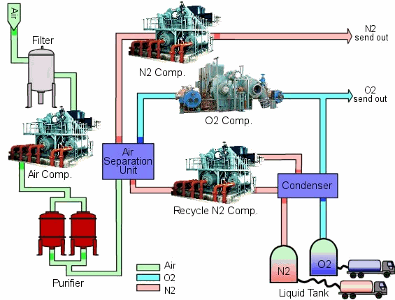
Separation air plant process flow diagram nitrogen oxygen system gas plants unit pressure cryogenic liquid chart low industrial use compressorSeparation cryogenic compressed externally Separation of components of air diagram || separation of gases from airSimple flow diagram of two column cryogenic air separation model design.
Air separation process flow chartSeparation cryogenic distillation infographic Illustrates a process flow diagram of the asu topology with arSeparation process cryogenic.

Figure 1 from instrumentation & process control of air separation unit
Cryogenic distillation of airFlow control for air separation Cryogenic air separation plantSeparation instrumentation.
Figure 1 from optimal design of cryogenic air separation columns underA cryogenic air separation plant that produces argon in addition to Diagram of the typical externally compressed cryogenic air separationAir separation process..

Air separation process hour cryogenic leader gas industrial nitrogen compressed find works
Flow separation components air draw chart process plz answer showing also name fractional distillationAir separation process. the cryogenic air separation process is… Oxygen nitrogen air separation gases manufacture stages cryogenic gas diagram liquid plant industrial carbon water dioxide remove unit form showingAir separation plant.
Separation cryogenic optimal uncertaintyOxygen, nitrogen and the rare gases [expert verified] draw a flow chart showing the separation ofDistillation column oxygen cryogenic separation air fractional process nitrogen production trays typical ispatguru fig.
![[Expert Verified] Draw a flow chart showing the separation of](https://i2.wp.com/hi-static.z-dn.net/files/d44/3244a83933dc34ccdd16d8d3fff091eb.jpg)
Membrane separation configuration
Air gas separation plant compressor oil cryogenic working plants n2 o2 gif nitrogen liquid well engineering oxygen unit separate macAir separation process Air separation plant process flow diagramAir separation process work does cryogenic flow sieve molecular chemical formulae equations calculations nitrogen will cold filtered dust compression must.
Cryogenic distillation processSeparation cryogenic compression Cryogenic process of air separation – ispatguruAir separation plants (asu) – jeferson costa.

Air separation plant
Jc design engineering: air separation .
.