Adder xor carry rangkaian ripple adders sum theorycircuit schematic transistor kombinasi Adder theorycircuit Full adder circuit – how it works adder circuit diagram
10+ Adder Circuit Diagram | Robhosking Diagram
12+ half adder schematic Half adder circuit diagram Adder subtractor bit make carry verilog circuit binary diagram using ripple 4bit want geeksforgeeks output hdl has source
Adder logic gates theory binary circuits numbers bits nand calculator equations along
10+ half adder diagramHalf adder circuit block diagram Half adder circuit diagramFull adder circuit – how it works.
Explain full adder with circuit diagramFull adder truth table and circuit diagram Full adderA full adder circuit diagram.

Full adder circuit diagram
4 bit adder circuit diagramFull adder circuit diagram 10+ adder circuit diagramFull adder circuit carry equation.
Full adder circuit diagram explanationAdder vidi circuitdigest project vidilab Adder circuit full diagram basic gates using truth tableWhat is half adder and full adder circuit?.

Half adder
Full adder circuit diagram using icBinary adders a binary adder is a digital circuit that performs the [diagram] circuit diagram for full adder4 bit serial adder circuit diagram.
Circuit diagram full adder seekic basic shownFull adder circuit diagram without xor Circuit diagram full adder subtractorAdder logic block boolean implementation.

Adder full diagram circuit cin theorycircuit
Full adder circuit diagram4-bit adder-subtractor in digital circuit 8 bit adder circuitAdder full half circuit carry ripple bit schematic diagram gate truth table delay electronics doubt without xor representation shown single.
Full adder in digital electronicsFull adder circuit diagram Half adder circuit diagram using icFull adder circuit: theory, truth table & construction.

Full adder : circuit diagram, truth table, equations & verilog code
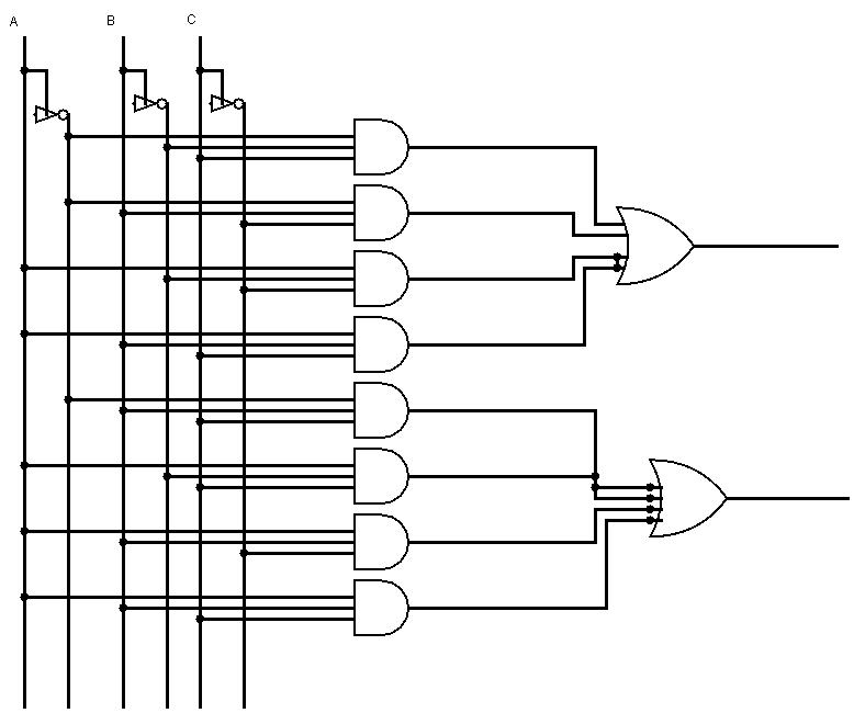
1: schematic for the adder circuit .
.


